BlowsMeAway Productions
Frequently Asked Questions
Please use these links:
Home -- Custom Wood Mics -- Ultimate Series Mics -- Bulletini® Mics -- Rackit! Mics -- Wireless Systems -- Kalamazoo Amps
Bulletizer-- Vintage Volume Control -- XLR Volume Control -- Mods, Repairs and Adapters -- Ordering and Pricing
 |
|
Designer and producer Greg Heumann |
|
| General | Q: What is the In-line Volume Control for?
A: The control provides harmonica players with the ability to quickly adjust volume during performance without having to be close to the amplifier, AND to get close to the amp to make adjustments without worry. This is useful for many reasons, such as setting the maximum volume attainable without feedback, adjusting for quieter harps (Low D comes to mind,) or "backing off" a bit when filling behind anothers' solo or vocal. The control positions the knob where it is not prone to "accidental adjustment." This can be a real problem with on-mic controls as you constantly re-adjust your cupping/holding hand position. You can move the control from mic to mic easily, making it far less expensive than adding built-in controls to individual mics. |
||
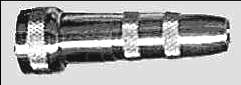
| Q: What was the inspiration for this product?
A: Many years ago, Switchcraft (manufacturer of many connectors for audio and radio frequency use) made the "Nr. 329" volume control shown at right. Today, it is a prized collector's item, and good examples sell for as much as $300. I wanted to reproduce the functionality of this control, but in an even smaller package and with better structural design. |
 |
||
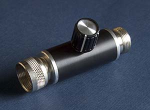
| Q: How does it work?
A: The control places a variable resistor, or "potentiometer", often referred to as a "pot", between the amp and microphone. The schematic diagram to the right shows how this is accomplished, and is the way both the Switchcraft control and my design work. The resistor places some load on the microphone, just as the amplifier itself does. |
Volume control schematic |
||
| At full volume, the pot's "slider" is at the far left of the resistor in the diagram. This offers the highest resistance to ground (minimal load on the mic) and least resistance to the amp (zero ohms). At lowest volume, the slider would be at the right side, effectively shorting the mic's output so that no signal goes to the amp. In this position, the volume control acts just like an "off" switch, but without the annoying click you might get with an ordinary switch. | |||
| Q: My mic is set up for 1/4 inch phone (also known as "guitar") cables. Can I use the control? A: Yes. I can provide a Switchcraft Type 44 adapter as shown at right for this purpose. In addition to the adapter, you need a cable with a standard 1/4" connector for the amp end and a Switchcraft female connector at the other. This will connect the volume control to your cable. You can buy these cables through HarmonicaMasterClass. I can also make custom cables with any connectors you like. I charge $20 plus $1.25 per foot. |
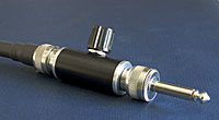
Volume control shown with |
||
| An alternative is to modify your microphone to use a Switchcraft connector in the first place. No more stepping on the cable and pulling it out of the mic while you're playing! Check out my Mods page - I cap provide this service. | |||
| Q: I really want to use my 1/4"guitar cable. I promise never to step on it and jerk it out of my mic during a solo.
A: This is the Switchcraft 332A. I sell these for $14.95. I also make custom controls and adapters with your choice of connectors - see the Mods and Adapters page. |
1/4" to Switchcraft adapter allows you to use a guitar cable with the control. |
||
| Q: I am set up for XLR cables . Can I use the control?
A: If your microphone is low impedance and you play through a PA, the best solution is my low impedance XLR volume control. If you use your low impedance mic with a harp/guitar amp, then you also need to use an impedance matching transformer. The product shown to the right is what you need. And if you want a combinated impedance matching transformer/volume control with your choice of connectors, I make those too - see the Mods and Adapters page. If your microphone is a high impedance mic I can make you a custom volume control. Some high impedance XLR mics have the mic signal on Pin 2, some have it on Pin 3 - so you must be able to tell me what you have, or send me your mic. You also must choose the kind of connector you want on the cable/amp side - Switchcraft or 1/4" female are common choices. See the Mods page for more info. |
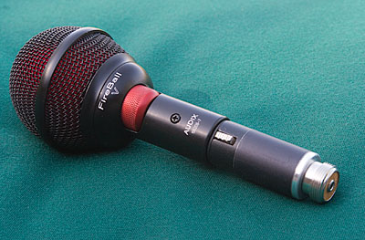
I make adapters like this one shown on an Audix Fireball V mic - XLR at one end, switchcraft at the other, an impedance matching transformer in between. |
||
| Tone | Q: Will it affect my tone?
A: The short and honest answer is "yes". The most important modifier is "for the better" and an equally important one is "but not much." Crystal element mics like older JT30's are likely to be most affected; dynamic (including controlled magnetic and controlled reluctance) mics aren't as affected. In any case, the impact is minimal, and many players don't notice any change. If you do, generally you can usually re-adjust your amp settings to compensate. There are many factors involved in amplified tone, the most important of which is technique! Other key ingredients are the amplifier and the microphone. Your technique will not change for better or worse, and your amp and mic combination will still exhibit their unique characteristics. You can also contact me about custom controls for special mics. Tone is affected as the volume is reduced, by reducing the high frequency response. When you overdrive your microphone into its distortion range, some of that distortion is comprised of high frequency signals. Reduction in volume will "take a little edge off." I personally like this - when I reduce the volume it is because I am trying to stick out less, usually when I'm filling as opposed to soloing. Solid state amplifiers tend to reproduce microphone distortion with a gritty, hard edge - losing a lot of the warmth associated with all-tube designs. The installation of a volume control will take just a little of this edge off - making the sound (in my opinion) much more pleasant. Note that the human ear is naturally less responsive to both high and low frequencies as volume is reduced as well. This is a documented phenomenon known as the "Fletcher-Munson Curve." Some of the reduction in highs comes from the control, but some comes from this as well. In the end, I say "Try it, you'll like it". And if you don't, I offer a money-back guarantee. Just return it within 7 days and I will refund your money. |
||
| Q: How can I minimze the control's effect on tone?
A: Easy. Just set up your amp and mic with the volume control installed. Set the control to full volume and adjust your amp for the loudest sound you want, along with the tone you want. If you already have a very dark tone, you may want to turn the treble, gain or presence controls up a tiny bit to restore any lost brightness. Voila! You're all set. |
|||
| Q: I heard that you should have a 1 Megohm or even 5 megohm pot to minimize effect on tone. Why did you choose a 100K pot? (Update: I switched to using 250K pots in about 2015.)
A: While it is true that a higher resistance pot puts even less load on the mic at full volume, there are significant disadvantages to using higher values. Most importantly, a useful volume range is available within only about 10 degrees of knob rotation. This makes it very difficult to make quick, subtle changes. I have seen schematics of circuits with additional components designed to offset this narrow control range problem, but these circuits have their own negative side-effects. The 100K pot (the same one, by the way, Shure ships with every 520-DX Green Bullet mic - the best selling harmonica microphone in the world) provides useful control over its entire 270 degree travel. As a rule, crystal mics are the most sensitive to the load placed on them by the amp and volume control. Solution: turn the amp up, dial up the treble and mid to compensate. If you're using a Bassman-style amp, consider substituting a 5 M-ohm resistor for the 1 M-ohm resistor wired across the input jacks. This resistor ALSO places a load on the cartridge and can reduce the performance of a crystal mic; the 5M resistor has less negative effect. I do build custom controls with 1Mohm pots. Dave Barrett and I have tested them. We agree they are absolutely the wrong solution for any dynamic, controlled magnetic or controlled reluctant elements. If you have a crystal or ceramic element, you might prefer the 1M version. Note the pot I use for this control has a 1/8" nylon shaft and therefore is not as rugged as the 1/4" aluminum shaft in my standard controls. However if you avoid "slamming" it against the "full" and "off" stops it should last a long time. Princing info at the bottom of the Mods and Adapters page. |
|||
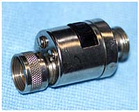
| Physical | Q: I was told that the center connector should have a big old wad of solder on it to ensure a good connection. Is that true? | ||
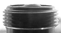
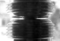
| A: No! There is a real art to soldering these connnectors properly, but to understand how they should be done, let's start by looking at one before it has been soldered.
In the photo at right, notice that the center connector (actually a rivet) stands above the remaining surface, even with no solder at all. |
 |
||
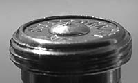
| In this photo, the "coupling ring" that would normally hold the two connectors together has been removed. You can see that the rivets touch easily - they don't need to be any higher. (The ground connection is normally made by the coupling ring.) |
 |
||
| I see many connectors like the one shown here. The wire was soldered into place above the level of the rivet, leaving a rough surface with a tiny contact area. The assembler flowed extra solder to try to cover it up. As the soft solder deforms under stress, this will almost certainly result in a bad connection during a performance. Be on the lookout - the only way to get the solder to bulge well above the rivet is if the wire protrudes above the rivet as well, and this is a bad idea! |
Wrong! |
||
| A properly soldered connector looks like this. The wire is held in place below the rivet surface as solder is applied. The solder should appear slightly depressed in the center, or flat. This leaves the entire ring of the rivet (which is made of much harder material than solder!) available as a flat connecting surface with a lot of surface area. |
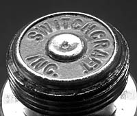
Correct |
||
| Service/ Structure |
Q: What if my connector needs service? Can it be disassembled?
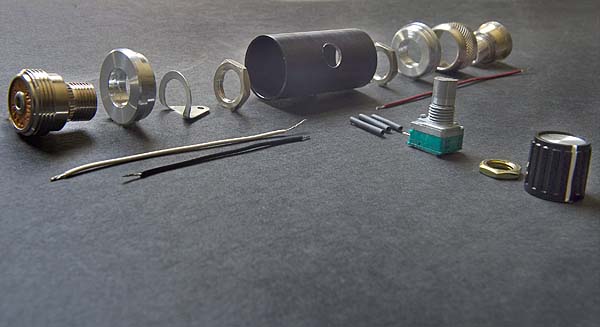
A: Yes, it can be disassembled. I would not recommend trying this without contacting me for some techniques to prevent damaging the unit. But I think once you see one, you'll rest assured that it won't fail in the first place. I truly believe it will last a lifetime without requiring any service. I use mine all the time and believe me, I don't want it to fail! I wanted to be sure it would be mechanically strong enough to endure the rather severe torque loads it might ancounter in normal use, and I sure didn't want any chance of a connector coming loose, spinning in the housing. The photograph below shows an "exploded parts diagram." The Switchcraft connectors have a knurled portion at the neck of the smaller threaded diameter. I machine the hole in the aluminum end-caps hole smaller than the diameter of this knurled portion. I then press the connectors into the end-caps with an arbor press, mechanically locking the connector to the end-cap. It can not spin! And to ensure it can't back out either, I add a nut, and a drop of Loctite® for added security. These assemblies are then press-fit into the aluminum barrels. This makes for an extremely strong joint. A drop of Loctite® is applied to these joints before fitting as well, just to be sure. |
||
|
|
 |
||
| I value your feedback! Please let me know what you think of the product! And of course, if you have any questions, feel free to ask. Click here to contact me. | |||
|
|
|||
| Copyright © 2007-2010 BlowsMeAway Productions | |||